Privacy statement: Your privacy is very important to Us. Our company promises not to disclose your personal information to any external company with out your explicit permission.
The charge pump application is essentially equivalent to a voltage doubler rectifier circuit in the circuit. In some places where high voltage and low current are required, a voltage doubler rectifier circuit composed of a charge pump is often used. The voltage doubler rectification means that a lower AC voltage can be used to "conform" a higher DC voltage with a rectifier diode and capacitor with lower withstand voltage. Charge pumps are generally divided into double voltage, triple voltage and multiple voltage charge pumps according to how many times the output voltage is the input voltage.
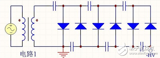
Voltage pump circuit diagramThe voltage pump circuit has a variety of structures, each with advantages and disadvantages. Common circuits are as follows:


These three circuits are all 6 times voltage pump circuits, each with its own characteristics. We usually say that every 2 times is the first order, denoted by N, the above circuits are all 3 orders, that is, N=3. If you want the output voltage to be different in polarity, just reverse all the diodes.
Advantages and disadvantages of three circuit voltage pumps1, circuit 1
The advantage is that the voltage on each capacitor does not exceed twice the secondary peak voltage U of the transformer, ie 2U, so a capacitor with a lower withstand voltage can be used. The disadvantage is that the capacitor is in series discharge and the ripple is large.
2, circuit 2
The advantage is that the ripple is small, and the disadvantage is that the voltage withstand voltage of the capacitor is high, and as N increases, the voltage stress of the capacitor increases. The voltage of the last capacitor in the figure reaches 6U.
3, circuit 3
It is an improvement of circuit 1. The advantage is that the ripple is much smaller than that of circuit 1, and the voltage stress of the capacitor does not exceed 2U. The disadvantage is that the circuit is complicated.
How does the voltage pump circuit diagram work?The circuit 1 is taken as an example to illustrate the working principle:

When the secondary output of the transformer is up and down, the current flows as shown. The transformer charges energy to the three capacitors of the upper arm.
When the secondary output of the transformer is up-down, the current flows as shown. The upper arm capacitor is charged through the secondary arm of the transformer.

If there is no load, in steady state, except for the leftmost capacitor, the voltage on each of the other capacitors is 2U, so the total output voltage is 6U. In fact, due to the poor carrying capacity of the high-order voltage doubler rectifier circuit, the output of a small power will cause a large drop in the output voltage. Assuming that the output current is I, the capacity of each capacitor is the same, C, and the AC power frequency is f, then the voltage drops to:

The output voltage ripple is:

The diode used in the voltage doubler rectifier circuit should have a maximum reverse voltage greater than. A high-voltage silicon rectifier stack is available, and its series model is 2DL. For example, 2DL2/0.2 means that the highest reverse voltage is 2 kV and the average rectified current is 200 mA. The capacitor used in the voltage doubler rectifier circuit has a relatively small capacity and does not require an electrolytic capacitor. The capacitor's withstand voltage is greater than 1.5x, which is safe and reliable in use.
Wyślij je do tym dostawcy
January 03, 2024
January 03, 2024

Privacy statement: Your privacy is very important to Us. Our company promises not to disclose your personal information to any external company with out your explicit permission.

Fill in more information so that we can get in touch with you faster
Privacy statement: Your privacy is very important to Us. Our company promises not to disclose your personal information to any external company with out your explicit permission.